 08-04-2010, 01:37 AM
AM Algorithm Machine
A Tiny Tester for Developing Parallel Algorithms
You can use this tiny tester, built from Parallax parts, for developing parallel algorithms and running tests for much larger machines (including large Propeller based parallel cluster machines under design and construction). It's a real time saver! The tester is an upgrade and a spin-off of the Minuscule BASIC Stamp Super Computing Machine. This is a tiny algorithm machine, simple to build, easy to use. The field of parallel clustering computing is relatively new to hobbyists. Developing techniques and methods is an important aspect of cluster computing to gain the greatest rewards and benefits from not only paralleled space but multiprocessors as well.
Features
- Operates in five BUS modes
- Serial & Parallel options
- Includes WIDE BUS
- Handles up to 200 step code
- Programs in PBASIC
- Very small footprint
- Builds with Parallax BASIC Stamp 1 Project Boards #27110
- Speakers & LEDs for output
- Twin 9-volt battery operated
SCHEMATIC

Use the above schematic to build the tester, then program it with parallel algorithms to test various interfaces and parallel configs. Provisions are made for converting between single wire, full duplex, and data buss interfaces.
_____________________
Overview
It doesn't matter if you're using stamps or props, parallel techniques work cross platform. Here's a chance to use a language that's been proven over time and develop routines for new parallel machines. The addition of the upgraded interface bus allows for trying out several hardware configurations such a one wire, serial full duplex, and data bus.
Criteria
The AM is currently being used with the UltraSpark 40 Supermicrocontroller Parallel Computing Machine and satisfies several conditions for testing the new series.
Interface
This versatile machine operates in four modes, which can be wired as single mode A, single mode B, or dual modes A & B, or simply C mode. Operate the AM using a single wire and serial PBASIC code commands or program the machine using the seven parallel port bits.
A - Single Wire Serial P0
B - Parallel Bus P3, P4, P5, P6, P7
A + B Dual BUS, as seen above
C - Parallel Bus Only P0, P3. P4, P5, P6, P7
Code and Parallel Algorithms
It is left up to the user to derive various parallel algorithms in PBASIC
code. However, as code becomes available, it can be posted in this thread. The 1st proposal is a split function task for n processors. In this example, one program is written that supplants itself into n processors and auto determines the work share for each processor. Time passes and the work conclusion is collected and concluded. It is ok to create a separate collection program.
10-12-2010, 07:15 AM Update 10.12.2010 NAME ESTABLISHED
This update includes the name AM - Algorithm Machine. This is a tiny minimal two core machine capable of quickly running tests on simple parallel algorithms. The second advantage of the machine is that it introduces a new wide bus for experimentation.
10-12-2010, 07:20 PM Update 10.13.10 REVISED SCHEMATIC
Revised Draft Schematic Posted
10-13-2010, 08:56 AM INTRODUCING WIDE BUS
A - Single Wire Serial P0
B - Parallel Bus P3, P4, P5, P6, P7
A + B Dual BUS, as seen above
C - Parallel Bus Only P0, P3. P4, P5, P6, P7
D - P0 - P7
Regarding bus modes. For a D mode, WIDE BUS, remove the LEDs and Peizo speakers to gain a parallel eight bit BYTE bus data array using pins P0- P7. Connect, P0 to P0, P1 to P1, P2 to P2 up to P7 to P7, confirming a protection resistor (220 ohm) across each port.
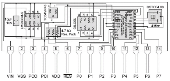
10-13-2010, 08:57 AM BS1 PROJECT BOARD SCHEMATIC

BASIC Stamp 1 Project Board Schematic - Use for Wiring the AM
Schematics may be difficult to find these days. Use this BS1 Project Board schematic when wiring two boards together to create the AM project. The 93LC56 chip is an EEPROM with 256 bytes size or 1/4th K. This holds up to 100 instructions. The microcontroller is a Microchip PIC16C56A running at 4MHz. This gives about 2,000 IPS Instructions Per Second. The serial PC interface runs at 4,800 BAUD for programming and debug. Power can be within the range of 6 to 15 volts.
Source / Sink Current per I/O.................. 20 mA / 25 mA
Source / Sink Current (device) ................ 40 mA / 50 mA
Power Consumption................................ 7 mA running (no loads); 5 mA Sleep (Rev B). On Rev B boards the power LED remains illuminated when the BASIC Stamp is in sleep mode
10-13-2010, 08:57 AM PROGRAMMING COMMANDS
BRANCH Branch to address specified by offset
BUTTON Monitor & manage button input; branch if button in target state
DEBUG Send variables and/or messages to PC for viewing
EEPROM Store user data in available EEPROM space
END Terminate program and enter low-power mode until reset
FOR...NEXT Create numerically controlled loop
GOSUB Unconditional branch to a subroutine
GOTO Unconditional branch to program address
HIGH Make pin an output high
IF...THEN Compare and conditionally branch to program address
INPUT Make pin an input
LET Optional designator for assignments
LOOKDOWN Search table; if found set output variable to target location
LOOKUP Set output variable to table data specified by offset
LOW Make pin output low
NAP Enter low-power mode for short period
OUTPUT Make pin an output
PAUSE Suspend program for 1 to 65,535 milliseconds
POT Read a 5 – 50 K variable resistance and scale result
PULSIN Measure width of an input pulse
PULSOUT Output timed pulse by inverting pin for some time
PWM Output analog level (requires external RC network for filtering)
RANDOM Generate a pseudo-random number
READ Read byte from EEPROM location
RETURN Return from a subroutine
REVERSE Reverse pin state; make input if output, output if input
SERIN Receive serial data, 300 – 2400 baud, N81 format
SEROUT Transmit serial data, 300 – 2400 baud, N81 format
SLEEP Enter low-power mode for 1 – 65,535 seconds
SOUND Generate tone or white noise
TOGGLE Make pin an output and toggle current state
WRITE Write byte to EEPROM location
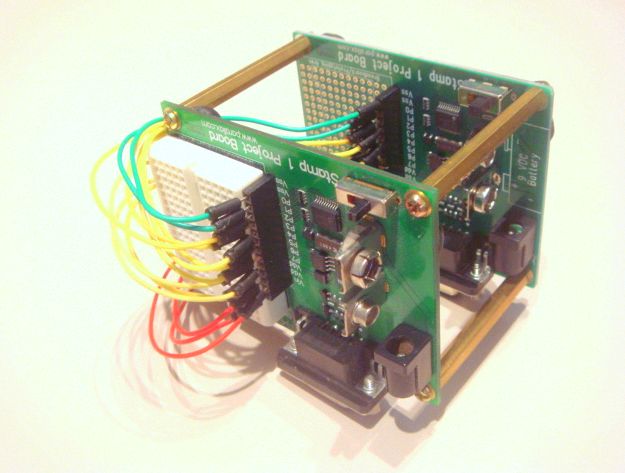
10-13-2010, 10:28 AM MORE PHOTOS
This view of AM - Algorithm Machine, shows a nearly cubical shape, wired in WIDE BUS mode. The solderless breadboard is used only on the top board. Wiring is made with the pin connectors. The bread- board is used for adding the Peizo speaker and LED outputs in other modes.
10-14-2010, 05:33 AM AM Algorithm Machine BS1-IC Experiment
Instead of using two Stamp 1 Project Boards, this experiment uses a BS1-IC in SIP form. A BS1 module (Parallax part number BS1-IC) plugs into the solderless breadboard on one Stamp 1 Project Board and extends its buss connections directly to the board. The following features result.
* Significantly Smaller
* Improves Wiring Efficiency
* Better Visibility
* Maintains both Peizo & LED Outputs
* Requires Only One Battery for Field Use
* Rewiring is faster
 |
| BASIC Stamp 1 Module |
 |
| BS1 Project Board |
Setup uses a Revision B Project Board and Revision C BS1-IC. The Project Board programs with a serial to USB converter, and has a choice of battery or power supply operation. Note, the on/off switch at lower right in the photo is especially handy for recycling power.
Schematic for rev. c was not found, however, the pinout of BS1-IC Rev. B can also be used for wiring Rev. C.
Note, this experiment is provided for pure academics. In actuality, to program the add-on BS1-IC SIP, add a small three pin programming port and a Parallax Serial Converter, then connect to the PC.